Clearance coupons: finding this machine's real tolerance in one 64-minute print
Every FDM machine has a minimum clearance below which parts fuse, and it is not in any spec sheet. This log prints a six-clearance coupon, corrects the two slicer compensations that decide the answer, and settles on the numbers to design against on this specific Voron.
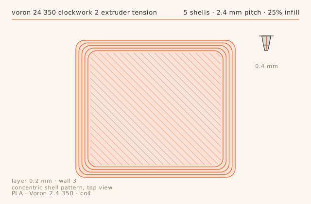
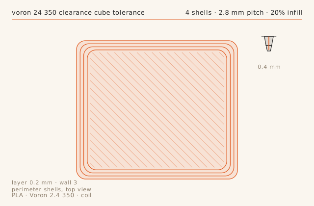
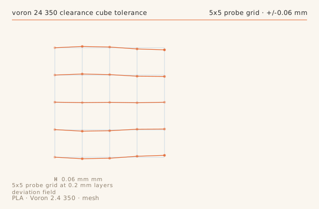
Slice diagramsDrawn from this entry’s own slicer settings.
Print record
- Machine
- Voron 2.4 350
- Material
- PLA
- Nozzle
- 0.4 mm
- Layer height
- 0.2 mm
- Walls
- 3
- Infill
- 20%
- Print time
- 1 h 4 min
- Published
- September 29, 2026
Measure the hole before you measure the clearance
The coupon failed for a reason that had nothing to do with clearance. An 8 mm nominal pin printed at 7.87 mm because hole compensation was set to zero, which made every slot 0.13 mm tighter than the drawing. Fix the hole error first: print a single pin-and-hole pair, measure with a pin gauge, and set hole compensation so the hole matches nominal.
In this slicer, hole compensation applies to all closed inner geometry, so adding +0.10 mm also pushed the coupon's outer wall out by 0.08 mm. That is why contour compensation came down to -0.02 mm at the same time. Two dials, one measurement pass.
The coupon design matters more than the print
A useful clearance coupon has six or eight pairs of identical features separated by a known increment, laid out far enough apart that a tight pair does not influence a loose one. I used 0.05, 0.10, 0.15, 0.20, 0.25 and 0.30 mm, each pair as a 20 mm long slot with a matching tongue, printed flat with the gap in the XY plane only.
Do not put the clearances in the Z direction on the same coupon. XY and Z clearances are governed by different error sources and mixing them makes the result unreadable.
What this machine actually holds
After correction, 0.15 mm is the tightest XY clearance that moves freely by hand, and 0.10 mm releases with light finger pressure but feels gritty and will wear. For a printed hinge or a sliding joint that has to work for a thousand cycles, 0.25 mm is the number to design to, with 0.15 mm reserved for parts that are assembled once and never moved.
Vertical clearance behaves differently: because layer thickness is 0.2 mm and the top of a layer is always slightly domed, a Z clearance below 0.20 mm will interfere no matter how well XY is tuned. Set Z clearances to 0.25 mm minimum.
Re-run the coupon after any flow change
Clearance is a function of extrusion width, and extrusion width changes whenever you change flow, pressure advance or nozzle. The coupon takes 64 minutes and 11 grams of filament. Re-print it after any of those changes and write the result next to the date, the way the rest of these logs do.
The current numbers are valid for PLA at 0.2 mm layers with a 0.4 mm nozzle and 0.038 pressure advance on this machine. Nothing else.
Failure chainWhat went wrong, what was done about it, and what came out the other side.
-
Step 01
Symptom
The 0.10 mm clearance pair on the coupon was welded solid; the 0.15 mm pair moved but with a gritty feel.
Fix
Measured with a pin gauge: an 8 mm nominal pin printed at 7.87 mm. Hole compensation was 0. Added +0.10 mm hole compensation and dropped contour compensation to -0.02 mm to keep outer walls from growing with it.
Result
The 0.15 mm pair moves freely with no grit. The 0.10 mm pair now releases with light finger pressure.
-
Step 02
Symptom
Outer dimensions of the coupon grew 0.08 mm after adding hole compensation.
Fix
Hole compensation in this slicer applies to all closed inner features and pushed the wall outward. Applied -0.02 mm contour compensation to compensate, then re-measured.
Result
Outer walls back to 40.00 / 39.98 mm, holes at +0.10 mm.
Dimensional check
- Feature
- clearance test coupon, six clearances from 0.05 to 0.30 mm
- Nominal
- 0.15 mm
- Measured
- 0.12 mm-0.03
- Tolerance
- ± 0.05 mm
- Note
- 0.15 mm nominal was the tightest clearance that moved freely by hand. Below that, parts fused on the 0.10 mm coupon and needed pliers.
Slicer profile
printer_model: Voron 2.4 350
layer_height: 0.20
perimeters: 3
infill: 20% grid
outer_wall_speed: 100
inner_wall_speed: 180
accel: 7000
nozzle_temp: 212
bed_temp: 60
part_cooling: 100%
pressure_advance: 0.038
xy_hole_compensation: 0.10
xy_contour_compensation: -0.02
What carried over
- Calibrate hole size with a pin gauge before you interpret a clearance coupon.
- Adding +0.10 mm hole compensation required -0.02 mm contour compensation to hold outer dimensions.
- Design to 0.25 mm XY clearance for joints that move; 0.15 mm is the absolute minimum.
- Keep Z clearances at 0.25 mm or more regardless of how well XY is tuned.
Verdict
The machine holds 0.15 mm XY and 0.25 mm Z. Both numbers are now written on the printer's maintenance card and should be re-verified after any extruder change.
Also on this machine Voron 2.4 350
-
Print log
A loose extruder latch cost 17 percent of the wall thickness and looked like a slicer problem
Intermittent under-extrusion with no pattern in the preview is almost never a slicer problem. This log is the diagnostic sequence that found it — measure the wall, measure the extrusion force, then adjust one thing at a time — and the narrow window between too loose and too tight on a Clockwork 2.
- MaterialPLA
- Nozzle0.4 mm
- Layer height0.2 mm
- Print time1 h 36 min
- Failure chain2
-
Tune profile
A PA6-CF profile for the Voron 2.4, and the two failures that dominate it
Carbon-filled nylon is the material where preparation matters more than settings. This is the profile that produced three consecutive clean three-hour prints: 285 C, no part cooling, 6 mm3/s, and a dry box on the machine at all times. It also covers the two failure modes that account for almost every bad PA6-CF print.
- MaterialPA6-CF
- Nozzle0.4 mm
- Layer height0.25 mm
- Print time2 h 58 min
- Failure chain2
-
Print log
0.6 mm nozzle, 0.4 mm layers: what vase mode really costs you
A 0.6 mm nozzle on a Voron turns a 96 mm vase into an 87-minute print, but it also changes the failure modes. This log covers the seam artifacts that come from running a long-melt-path nozzle at high volumetric speed, and the one region of the model where cooling has to be handled differently.
- MaterialPETG
- Nozzle0.6 mm
- Layer height0.4 mm
- Print time1 h 27 min
- Failure chain2